
Detector Striping
Landsat data are systematic, geometric, radiometric, and terrain corrected to provide the highest quality data to the user communities. Occasionally, anomalies occur and artifacts are discovered that require research and monitoring.
Return to Landsat Known Issues Overview
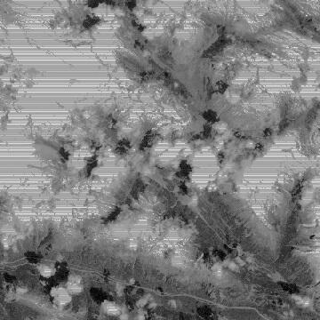
Any image in which individual detectors appear lighter or darker than their neighboring detectors is said to have striping. True striping, or "calibration striping", only occurs during calibration processing and is caused by incorrect relative detector gains, which cause single detectors within the image to be brighter or darker than their neighbors, creating stripes along the scan.

Striping is expected in L0 data and is not considered an artifact at this stage. Most Landsat 7 products do not exhibit true striping, but striping may exist in Level-1 (L1) data from earlier Landsat sensors. In general, striping is correctable by reprocessing the data with accurate relative detector gains.
When striping is visible only over bright, saturated targets, such as snow or clouds, it is known as saturation striping. Saturation striping is normal and expected in Landsat Level-1R products, as there will be minor differences in detector calibration when the 8-bit raw data are converted to 16-bit radiometrically corrected data. These calibration differences are less than one 8-bit Digital Number (DN), so when the data are converted back into 8-bit data for the Level-1 Systematic (Corrected) (L1G) product, the striping will disappear.
Saturation striping may also appear in some Landsat 7 ETM+ gain-change scenes. In gain-change scenes, part of the scene is converted from one gain setting to another. If high gain data with a small dynamic range is converted to low gain data with a large dynamic range, it may saturate at a value less than 255 DN. The processing system does not then recognize it as saturated data and may cause striping in the process of radiometric correction.
Saturation striping in Level-1 Radiometric (Corrected) (L1R) scenes or L1G gain-change scenes is expected and is not a cause for concern. If saturation striping is visible in a normal L1G product, corrections need to be made to the calibration of the instrument.

Band 6 high gain data exhibited prominent striping in Landsat 7 ETM+ data processed to Level-1 prior to November 23, 1999. This striping was not caused by an incorrect calibration, but by a software bug in the ground processing systems, which was subsequently corrected. The Band 6 striping artifact did not affect any of the reflective bands on the ETM+, nor did it affect the Band 6 low gain data.

A form of striping that affected earlier Landsat instruments is transmission striping. Because of the format in which data were downlinked from the satellite, data could be lost from a single detector at a time. Usually, several of these losses occurred at the same time, creating colored stripes when viewed as part of an RGB image. This form of striping is not correctable.