
Elevation-Derived Hydrography READ Rules: Artificial Path
An abstraction to facilitate hydrologic modeling through open waterbodies (Figure 33 and Figure 34).


Delineation
The limit of an Artificial path feature is defined as the connection between the inflow and outflow points of an in-line polygon, the line through a head or terminal open waterbody connecting to the inflow (for terminal) or the outflow point (for head) (Figure 34).
Representation Rules
Delineate features as points, lines, or polygons based on their area or length along different axes (Table 20).
| Kind of feature object | Area | Shortest Axis | Longest Axis |
| 0-dimensional (point) | -- | -- | -- |
| 1-dimensional (line) | -- | greater than 0 | -- |
| 2-dimensional (polygon) | -- | -- | -- |
Special Conditions
Artificial Path Features Around Islands
- Islands smaller than 1 acre shall not be delineated unless they were in the original breaklines used for hydroflattening the DEM.
- Group small islands into large “island areas”.
- IfSAR
- If islands smaller than 1 acre are present in the original breaklines, are no more than 30 meters apart, and cover more than an acre combined within the channel, treat the combined islands as an “island area” and only place Artificial path features around the group, not within them. The “island area” follows the same rules as an individual “island area”.
- Lidar
- If islands smaller than 1 acre are no more than 16 meters apart and cover more than a tenth of an acre combined within the channel, treat the combined islands as an “island area” and only place Artificial path features around the group and not within them. The island area would follow the same rules as an individual island area.
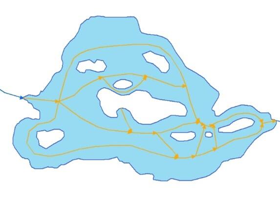
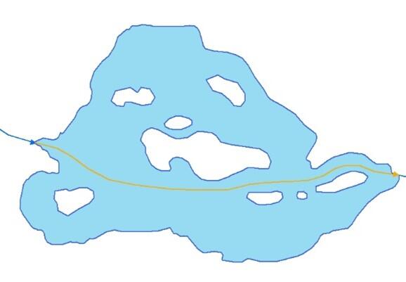
- Avoid tracing Artificial path features around all the islands (Figure 35). Artificial path features through waterbodies shall follow the shortest path while connecting to all inputs and outflowing channels (Figure 36).
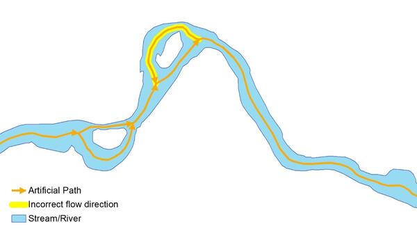
- Artificial path features represent the direction of flow and shall not loop back causing some flow to go upstream around islands (Figure 37).
- IfSAR
Data Extraction
Capture Conditions
Artificial path features shall be placed in all polygons except isolated Lake/pond features. Artificial path features shall represent the shortest path from the inflow to the outflow without crossing through banks or islands.
Attribute Information
FClass 1— Hydrography feature defined within the collection criteria of the elevation-derived hydrography specifications.
FCode 55800—Artificial path (abstraction to facilitate hydrologic modeling through open waterbodies).
EClass 2— Linear feature that follows elevation surface.
Source Interpretation Guidelines
None.