
Creating the Geometric Network Manually
This article describes the manual process for creating a geometric network using the ESRI out-of-the-box elements in ArcCatalog. Be aware that you must have the STANDARD (ArcEditor) license or above ArcGIS software to use this process.
► NOTE: This should not be used in NHD Jobs except when recommended by the Regional POC. This is mainly for users working with Staged datasets and can't use the NHD Utilities NetworkBuild utility. This also does not populate the NHDFlow table.
Creating the ENABLED domain and field (required for processing)
- Right-click the appropriate GDB ► Properties
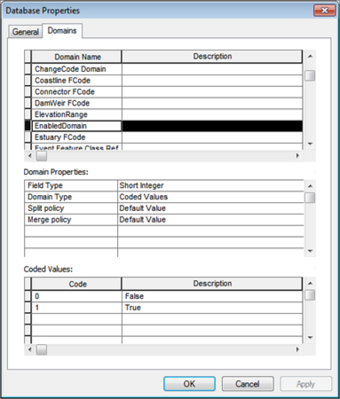
- In the Database Properties dialog, select 'Domains' and go to the bottom of the Domain Name list.
- Create a new domain name: 'EnabledDomain'
- In the Domain Properties:
- Field Type = 'Short Integer'
- Domain Type = 'Coded Value'
- The rest should be default value
- In the Coded Values dialogue:
- Code = '0', Description = 'False'
- Code = '1', Description = 'True'
- Close the dialog and right-click on the 'HYDROGRAPHY/NHDFlowline' feature class
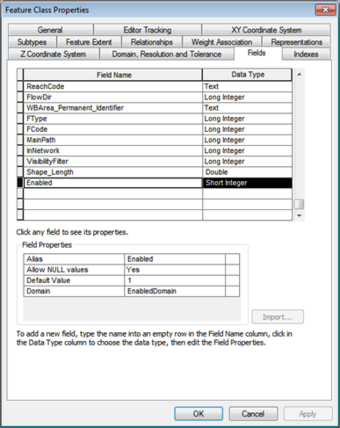
- In the Feature Class Properties 'FIELD" tab, go to the last empty box...
- Field Name: 'Enabled'
- Data Type: 'Short Integer'
- In the Field Properties box:
- Alias = 'Enabled'
- Allow NULL Values = 'Yes'
- Default Value = '1'
- Domain = 'EnabledDomain'
► NOTE: When created in ArcCatalog, the field will have no values. Users must open the field and populate the 'ENABLED' field using Field Calculator. The recommended setting is to enable ALL features (setting = 1), but users could decide to enable only features where the FlowDir is set to 'WithDigitized'.
FlowDir has two settings - '1 = WithDigitized' and '0 = Uninitialized', users could use this field to set the ENABLED field.
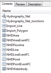
Creating the Geometric Network
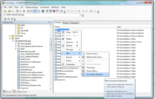
Right-click 'Hydrography' dataset ► 'New' ►'Geometric Network'.
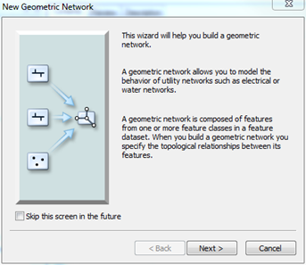
► Click 'Next' (User may or may not see this screen depending on if they’ve chosen to skip the screen previously).
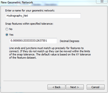
Accept the default name or change to 'HYDRO_NET' (preferred NHD naming convention).
Select 'Yes' to Snap features within the specified tolerance. Users can accept the default tolerance or set it to the NHD standard of '0.0001 Decimal Degrees' OR if a projected dataset use 1 meter.
► Click Next.
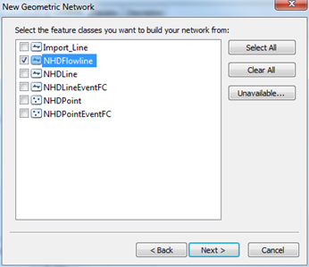
Check 'NHDFlowline' as the feature class to build the network.
►Click 'Next'.
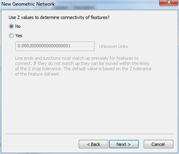
Select 'No' to use Z values.
►Click 'Next'.
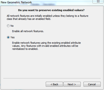
Keep the default option: 'Yes' (This uses the Enabled field created above).
►Click 'Next'.
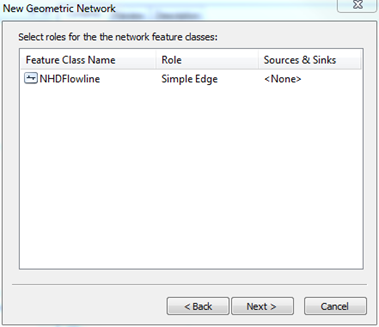
Accept the default Simple Edge setting.
►Click 'Next'.
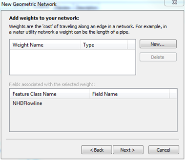
Accept the default. (do not assign any weights).
►Click 'Next'.
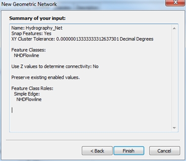
Review summary and select 'Finish'.
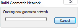
Processing dialog will appear.
Once complete, data will be updated with Geometric Network available.
► NOTE: In the root of the GDB folder there may be an error table created if geometric network errors are discovered. Refer to NHD Tips: Surveying Network Build Errors for these error codes.
Set Network Flow Direction (does not use the NHDFlowline attribute FLOWDIR)
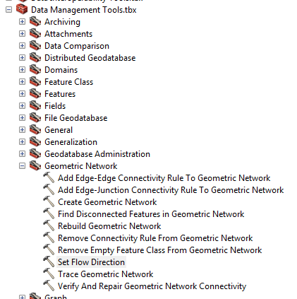
From Data Management Toolbox select Geometric Network -> Set Flow Direction
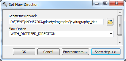
Select the Geometric Network created above and choose the WITH_DIGITIZED_DIRECTION Flow Option. Click Ok to run. (NOTE: Only ENABLED features will have the Flow Direction set)
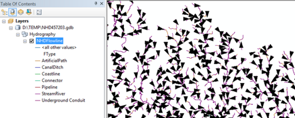
Display NHDFlowline data in ArcMap. Turn on the Utility Network Analyst Toolbar and Choose Flow ->Display Arrows. This will display the data with flow direction arrows to confirm the flow direction has been properly set.
*Any use of trade, product, or firm names is for descriptive purposes only and does not imply endorsement by the U.S. Government.