Aerial Camera System Boresight Development and Deployment
Plane-mounted aerial camera systems are used across the U.S. Department of the Interior for science, resource monitoring, emergency management, and disaster recovery, among many other applications. A critical step in deploying aerial cameras is calibrating these systems to ground control points (GCP). This allows the camera systems, when combined with photo rectification software, to precisely align aerial photos to each other and to their true position on the ground. After the photos are correctly aligned, one large seamless super photo (a photo mosaic), can be created.
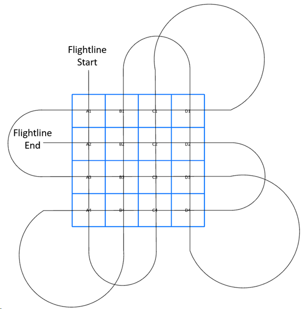
A field of GCPs collected together in a single area is called a boresight (figure 1). A boresight is simply a collection of GCPs in an established grid. This allows any plane-mounted aerial camera system the opportunity to collect imagery and be calibrated.

Figure 1: A mocked-up boresight showing how an airplane with an installed aerial camera system would cover the boresight installation to collect imagery of all quadrants (A1 – D4) while also ensuring overlapping photography is gathered.
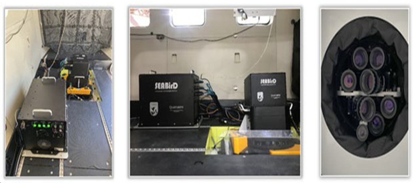
The U.S. Fish and Wildlife Service’s (USFWS) Migratory Bird Surveys Branch, in cooperation with staff from the USGS Upper Midwest Environmental Sciences Center, is investing in the creation of two boresight locations for the calibration of USFWS plane-mounted camera systems (figure 2).

Figure 2: This is an example of a plane-mounted camera system showing the USFWS SEABirD (Safe, Efficient Aerial Bird Detection) seven-camera array.
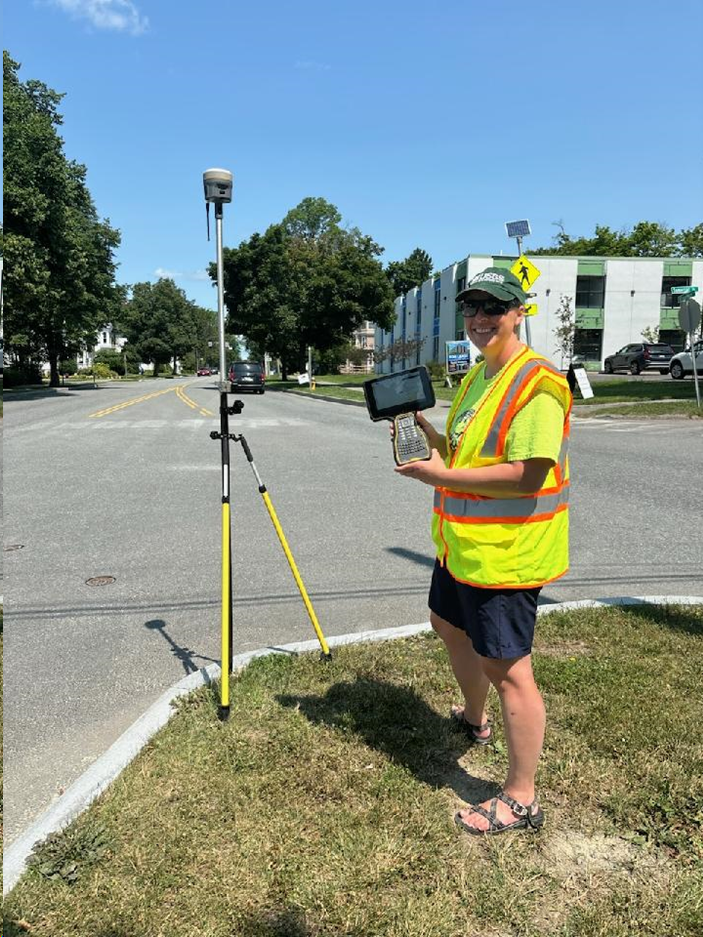
Each boresight location will consist of a 2-mile by 2-mile square grid subdivided into a collection of ½-mile by ½-mile squares. These ½-mile by ½-mile squares will have 10-15 GCPs selected and surveyed. Each GCP will be a preexisting object, structure, or marking on public land, and these will be surveyed for a high-precision geospatial location (accuracy of better than 4.5 cm vertical and 1.5 cm horizontal). Crews will be using high-precision Global Positioning System (GPS) survey units to collect data at each point, as well as documenting the visual appearance of the GCP (figure 3).

Figure 3: High-precision GPS unit collecting ground control point data.
The final product from this work will be one boresight installation in Bangor, Maine, and one boresight installation in Monroe, Louisiana along with associated GCP metrics, geospatial data, and installation ground photos published for use by the general public.
Plane-mounted aerial camera systems are used across the U.S. Department of the Interior for science, resource monitoring, emergency management, and disaster recovery, among many other applications. A critical step in deploying aerial cameras is calibrating these systems to ground control points (GCP). This allows the camera systems, when combined with photo rectification software, to precisely align aerial photos to each other and to their true position on the ground. After the photos are correctly aligned, one large seamless super photo (a photo mosaic), can be created.
A field of GCPs collected together in a single area is called a boresight (figure 1). A boresight is simply a collection of GCPs in an established grid. This allows any plane-mounted aerial camera system the opportunity to collect imagery and be calibrated.

Figure 1: A mocked-up boresight showing how an airplane with an installed aerial camera system would cover the boresight installation to collect imagery of all quadrants (A1 – D4) while also ensuring overlapping photography is gathered.
The U.S. Fish and Wildlife Service’s (USFWS) Migratory Bird Surveys Branch, in cooperation with staff from the USGS Upper Midwest Environmental Sciences Center, is investing in the creation of two boresight locations for the calibration of USFWS plane-mounted camera systems (figure 2).

Figure 2: This is an example of a plane-mounted camera system showing the USFWS SEABirD (Safe, Efficient Aerial Bird Detection) seven-camera array.
Each boresight location will consist of a 2-mile by 2-mile square grid subdivided into a collection of ½-mile by ½-mile squares. These ½-mile by ½-mile squares will have 10-15 GCPs selected and surveyed. Each GCP will be a preexisting object, structure, or marking on public land, and these will be surveyed for a high-precision geospatial location (accuracy of better than 4.5 cm vertical and 1.5 cm horizontal). Crews will be using high-precision Global Positioning System (GPS) survey units to collect data at each point, as well as documenting the visual appearance of the GCP (figure 3).

Figure 3: High-precision GPS unit collecting ground control point data.
The final product from this work will be one boresight installation in Bangor, Maine, and one boresight installation in Monroe, Louisiana along with associated GCP metrics, geospatial data, and installation ground photos published for use by the general public.

