
Elevation-Derived Hydrography Data Acquisition Specifications: Delineation of Hydrographic Features Requirements
Elevation-Derived Hydrography Data Acquisition Specifications
Delineation of Hydrographic Features Requirements
Hydrographic features shall be captured with either 3D point, line, or polygon geometry (Table 11). Some features may be collected as either 3D lines or 3D polygons, determined by the minimum area or length of shortest axis (Appendix 1). EClass indicates how features are used in elevation surface treatments. FClass indicates how the features are used in hydrography products.
Elevation-Derived Hydrography Feature Collection
- The correct geometry shall be used to capture each feature type.
- At minimum, a hydrographic feature collection shall do the following (Figure 4):
- Capture all features that a have a feature type in Table 8 present in the National Hydrography Dataset (NHD) and detectable on the elevation surface.
- Capture any additional features meeting capture conditions described in Appendix 1.
- New Hydrographic features shall be collected for the following reasons (Figure 5):
- If there is clear evidence of the feature on the elevation surface, such as
- Contour lines derived from the elevation surface.
- Geomorphic derivates as defined in Appendix 3.
- If there is clear evidence of the feature using an appropriate ancillary data source (Table 14).
- If a method has given good results for delineation of stream channels or other features and is quality assured using lidar data and high-quality ancillary datasets.
- If it is necessary to connect a hydrographic network.
- If there is clear evidence of the feature on the elevation surface, such as
- All criteria described in the following special cases shall be met.

Special Cases
12-Digit Hydrologic Unit Consistency
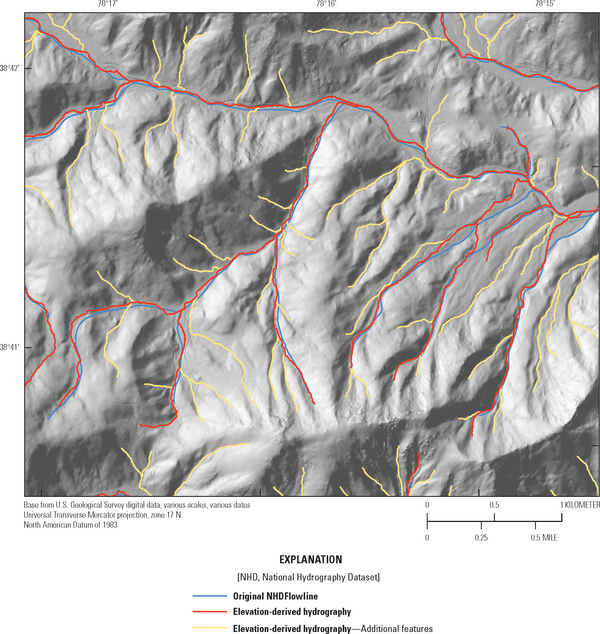
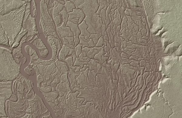
The original NHD was digitized from individual 7.5-minute quadrangle map sheets compiled at different times, by many individuals, using varied sources; therefore, some areas of the country have hydrography represented at different densities. These discrepancies are due to differing source material or standards and procedures and are not due to differences in geomorphology or hydrologic conditions (Figure 6). To create a more consistent and representative depiction of national hydrography, new features shall be collected within 12-digit hydrologic unit boundaries and areas with line density inconsistencies shall be made consistent with the most densely collected part of the 12-digit hydrologic unit (Figure 7).
In cases where prior local resolution or lidar-derived projects exist, discontinuity between feature density can occur. These discrepancies are often along county or other political boundaries (Figure 8). The same rules apply as those with quadrangle-line differences: linework shall match the densest representation of hydrography within a 12-digit hydrologic unit, unless channelization is not detectable within the elevation surface. Where geomorphology, geology, or other terrain features create actual differences in stream density, the natural representation of features that depicts the disparity in density should be captured.
Summary Guidance for Consistency
- New features collected within 12-digit hydrologic unit boundaries shall be evaluated for line density inconsistencies (Figure 6). New features shall be collected to be consistent with the most densely collected part of the 12-digit hydrologic unit (Figure 7).
- Where geomorphology, geology, or other terrain features create actual differences in stream density within the FDPA, the natural representation of these features shall reflect the density disparity.
- If a geographic area has an extremely dense stream network collected to meet local needs, a less detailed depiction of adjacent areas should be corrected when elevation-derived hydrography is collected. (Figure 8).


Bridge Locations
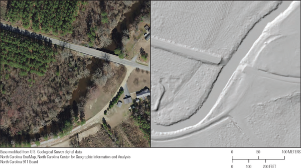
- Surface points at bridges are removed from the bare-earth elevation surface to ensure continuity of water features beneath and that shorelines are followed (Figure 9). No connector feature is required if the bare-earth elevation shows a continuous water feature where a bridge was removed.
- If a bridge is not removed, a hydrographic feature below a transportation feature shall be regarded as a Connector: Culvert (FCode: 33401).
- A culvert must be a separate feature, with nodes matched (snapped) to the up and downstream hydrographic features at each end.
- Elevation attribution (EClass=3) shall identify the culvert separately (Figure 10).
- If a polygon feature contains a culvert, the polygon shall not be split. The culvert feature shall be delineated on the Artificial path feature within the polygon feature.
- See the Connector: Culvert section of Appendix 1. for more information.
- See Connector: Terrain Breach if artifacts causing obstructions are present on the elevation surface.

Headwaters at Roads
- Identify streams with an initiation (headwater) point within 100 feet (ft) or 30 m of a road (Figure 11).
- If a stream channel is visible (in imagery or a DEM) upstream from a road, extend the Stream/river through the road using the rules described for delineation of Connector: Culvert features, and extend the Stream/river at least 100 ft or 30 m upstream from the road intersection.
- If a stream channel is not visible upstream from a road, but there are other indications that a culvert is present at the intersection of the road allowing flow to continue into the Stream/river, extend the Stream/river to the road and add a culvert feature through the road. It is not necessary to extend the Stream/river upstream from the culvert if no channel visible.
- If a stream channel is not visible upstream from the road, and no other indication of a connection between the upstream area and the headwater exist, no action is required.
- See the Stream/river section of Appendix 1 for more information.

Depressions
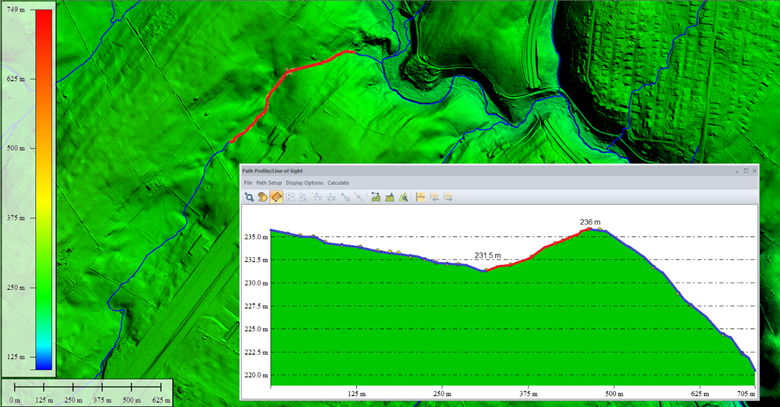
The following applies to linear features that need to rise from a depression greater than the vertical threshold (2-meter deep in IfSAR, 1-meter deep in lidar), have a channel downstream, and are outside of karst or thermokarst areas (Figure 12).
- Linear features exiting a depression shall be split at the point where the depression ceases to rise, and downstream monotonicity is possible.
- The segment from the lowest point of the depression to the high point at the edge of the depression shall be coded as a Connector: Indefinite Surface feature (Figure 13 and Figure 14).
- If the z-values of Connector: Indefinite Surface feature’s vertices cannot be downstream enforced,
- Add a comment to the feature stating, “Downstream monotonicity cannot be enforced through depressions in the surface.”
- Assign FlowClass = 2
- Assign EClass = 2
- The segment downstream of the split shall be coded as the appropriate feature class and downstream monotonicity shall be enforced.
- Indefinite surface downstream of a depression
- If a Connector: Indefinite Surface feature is required downstream of a depression, the portion of the feature inside of the depression shall have a comment stating, “Downstream monotonicity cannot be enforced through depressions in the surface.”
- The Connector: Indefinite Surface feature shall be split at the highest point out of the depression and the downstream Connector: Indefinite Surface feature shall be monotonic with no comment added (Figure 14).


When deciding whether to use a Connector: Indefinite Surface or a Connector: Terrain Breach feature, note that a Connector: Terrain Breach feature will not have a depression before the rise (Figure 51). Connector: Terrain Breaches are used when there is steady flow across the surface before encountering an obstacle blocking the flow. Connector: Terrain Breach features provide a method to bypass a typically short obstacle rising from the surface. A Connector: Indefinite Surface feature typically connects upstream and downstream features in channels over terrain with no detectable channels on the elevation surface but can also be used to navigate out of a depression (Figure 12).
Complex Interlacing Channels
- An area of complex channels is an area where a stream or river flows in an intricate network of interlacing channels with no permanent, primary channel.
- The Area of Complex Channels polygon feature type (FCode 53700) defined in the NHD is not included in the acquisition of elevation-derived hydrography.
- Hydrographic features falling within the previously defined area of complex channels shall be collected as Stream/river features (FCode 46000), Connector: Indefinite Surface (FCode 33404), Connector: Terrain Breach (FCode 33405), or other feature types as appropriate.
- No loops shall be present (see Topology Rules).
- Areas of complex channels previously identified in the NHD can identify areas where these guidelines shall be followed.
- Ancillary sources may also help identify areas of complex channels. Their use shall be noted in the Comment field and in the metadata.
- In areas of complex interlaced or braided channels, at least five channels present in the elevation surface shall be delineated.
- Appendix 1shall be followed to determine if streams are represented as line or polygon features.
- Intersecting features shall not have a valency/confluence greater than five.
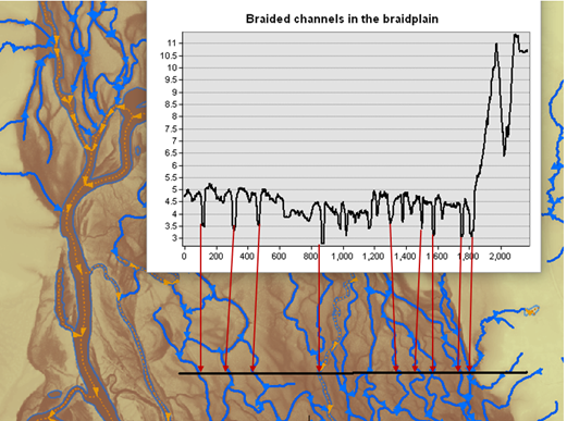
- Channels delineated shall be the most prominent either in width or depth (Figure 15).
- In IfSAR-based hydrography derivation, channels deeper than 2 meters and longer than 2000 meters are considered prominent.
- In lidar-based hydrography derivation, channels deeper than 0.5 meters and longer than 1000 meters are considered prominent.
- If multiple smaller channels are present, delineate channels that are evenly distributed throughout the entire braidplain to ensure the entire area is represented.
- If more than five channels are present efforts should be made to match the channel feature density delineated in the NHD.
- If the elevation does not include evidence of channelization to meet past NHD delineations, add an explanation to the collection report in the final delivery.
- Appendix 1shall be followed to determine if streams are represented as line or polygon features.
- Dynamic mid-channel bar deposits found in braided channels shall not be considered islands or follow island depiction guidelines. Multiple small mid-channel bars may be combined to appear as one area, but it is most important to maintain the characteristics of the braided channel being depicted.
- Large mid-channel bars or collections of bar deposits should typically have flowpaths on both sides. Large mid-channel bars or bar deposits are:
- Ten acres or more for IfSAR-based delineations.
- Four acres or more for lidar-based delineations
- Large mid-channel bars or collections of bar deposits should typically have flowpaths on both sides. Large mid-channel bars or bar deposits are:
An example of an area with multiple, interlacing channels is shown in Figure 16. The complex braided system is difficult to capture in its entirety and can be captured with a representative subset of channels, evenly spaced through the area. At least five major channels must be captured. Any features that have been hydroflattened or meet the 2-dimensional (2D) feature capture conditions (Appendix 1) shall be delineated as polygons, with Artificial path features. Narrower channels shall be captured that represent the complex nature of the area, but it is not necessary to include every channel. Both densities represented in Figure 17 and Figure 18 are acceptable for the represented area of complex braided stream features.


Low Relief Areas
In areas with no channel deeper than one meter in lidar or two meters in IfSAR below the surrounding DEM surface for 500 (lidar) and 1000 (IfSAR) meters, geomorphic derivatives indicate may indicate a channel is present, in such cases connector and Stream/river features may be placed to maintain the network but are otherwise not required (Figure 19). See Connector: Indefinite Surface Connector in Appendix 1 and Appendix 3 for information about connecting channelized features through un-channelized terrain.

Inclusion or Omission of NHD Waterbody Features
When developing elevation-derived hydrography for delivery to the USGS, waterbody features from the NHD shall be represented in the final hydrography network (Figure 20 and Figure 21. All updated features included for delivery shall be delineated in accordance with elevation-derived hydrography specifications and requirements.
Additional waterbody features not present in the NHD may be captured if they are a) present in the hydroflattening breaklines and meet the minimum size requirements, or b) present in the elevation surface and meet the minimum size requirements for capture of that feature type. (Appendix 1).
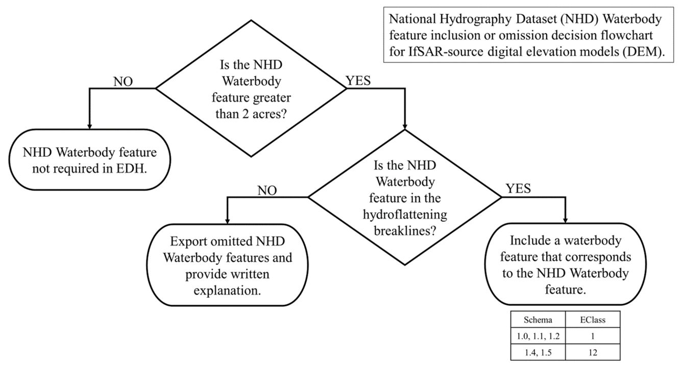
- All NHD Waterbody features that are:
- Greater than 2 acres in a DPA using IfSAR-source DEMs, or 0.25 acres in a DPA using lidar-source DEMs and are also found in the hydroflattening breaklines shall be included in the final delivery to the USGS.
- Greater than 2 acres in a DPA using IfSAR-source DEMs and were not found in the hydroflattening breaklines shall be exported to a NHD waterbody omission geopackage with a comment explaining their omission.
- In a DPA using IfSAR-source DEMs, if a waterbody is hydroflattened or otherwise discernible, and does not contain a breakline, it may be added to the elevation-derived hydrography delivery but is not required.
- Greater than 0.25 acre in lidar-source DEMs that were not found in the hydroflattening breaklines and:
- Detectable on the elevation surface shall be appropriately delineated and included in the final delivery to the USGS, or
- Not detectable shall be exported to a NHD waterbody omission geopackage with a column explaining their omission.
- NHD Waterbody features less than 2 acres in IfSAR-source DEMs or 0.25 acre in lidar-source DEMs are not required to be included in the final delivery. Some projects may have special capture conditions approved by the USGS.
- Add notes to the exported NHD waterbody features, in a text field named “Comment,” 255 characters in length, explaining why the NHD waterbody features are excluded, including in the following cases:
- If the NHD Waterbody feature in a different, non-overlapping location, it shall be noted that the feature is in present but in a new location.
- Comment: “NHD waterbody included in updated location.”
- If the NHD Waterbody feature is no longer present on the DEM it shall be noted that the feature no longer exists.
- Comment: “NHD Feature not present on elevation surface.”
- If the hydroflattening breakline overlapping the NHD Waterbody feature is less than 2 acres in IfSAR-source DEMs or 0.25 acre in lidar-source DEMs, it shall be noted that the corresponding breakline does not meet the minimum size capture conditions.
- Comment: “The breakline corresponding to this NHD Waterbody does not meet the minimum size capture conditions.”
- If the NHD Waterbody feature in a different, non-overlapping location, it shall be noted that the feature is in present but in a new location.
- If the NHD Waterbody feature is less than 2 acres in IfSAR-source DEMs or 0.25 acre in lidar-source DEMs, it does not meet the minimum size capture conditions and does not need to be exported or documented.
- Other reasons not listed here shall be noted and explained in detail in the collection report.
- Use a standardized comment throughout delivery if the condition occurs more than once.

Infrastructure Areas
Connector (33400) features shall be used to connect hydrographic features in areas where there is no clear channelization or flowpaths and evidence of built environments on the elevation surface (Figure 22). These Connector features shall be used where subsurface stormwater systems or long pipes are used to divert water underground for short to relatively long distances. In developed or urban landscapes Connector features to traverse areas where subsurface paths and connections are unknown. A Connector feature provides the approximate location of subsurface infrastructure connectivity so that the hydrography network can be continuous between upstream and downstream visible channels.
- If subsurface stormwater systems are available, the primary path through subsurface infrastructure can be included as the infrastructure connector.
- Secondary or minor subsurface connections should not be coded as part of the network and shall be coded as FClass = 2, EClass = 0.
- The Connector feature shall pass through a developed area likely containing a subsurface pipe and/or stormwater system where the subsurface connections are not known.
- Comment field shall contain “Infrastructure - unknown subsurface connection.”
- FClass field shall equal 1 (Hydrographic feature defined within the collection criteria of the elevation-derived hydrography specifications.)
- EClass field shall equal 3 (Linear feature used for breaching.).
- If subsurface connections are mapped and available as ancillary data, the primary path between features within channels on the elevation surface should be used.
- Comment field shall contain “Infrastructure - subsurface connection.”
- FClass field shall equal 1 (Hydrographic feature defined within the collection criteria of the elevation-derived hydrography specifications.
- EClass field shall equal 3 (Linear feature used for breaching.).
- The elevation of the downstream end node shall be at or below that of the upstream start node within the network to maintain downstream monotonicity (FlowClass = 1).
- Any surface channelization shall be captured as the appropriate FCode, with limited use of Connector features to provide network connectivity.
- If prominent ditches or canals are on the elevation surface and divert water around obstructions, capture those as Canal/ditch features rather than placing connector features used for infrastructure through a developed area. Canal/ditch features can connect to Connector features used to traverse infrastructure to create flow connectivity.
- Connector features used to connect flow infrastructure through areas with infrastructure:
- May connect features with channelization at an upstream point, through developed areas with no channelization, to downstream features within channels on the elevation surface.
- May be used to connect through large buildings or parking areas.
- Shall not be used if it is unlikely that the connection has underground stormwater pipes.

The Connector feature used to connect flow through infrastructure is not used:
- To traverse transportation features (see Connector: Culvert) unless the transportation features are within a densely developed area. See Figure 22 for an example of roads traversed by an Infrastructure Connector.
- To bypass evident natural channelization in a developed area or urban setting. This connector type can link the network through large buildings, parking areas, or through urbanized areas.
Ice Masses
A drainage network may need to be delineated in areas with ice masses (glaciers). In most cases, a channel will not be detectable through an ice mass, so a Connector: Indefinite Surface (FCode 33404) feature shall be used to for connectivity (Figure 23). If a Connector: Indefinite Surface feature is used, include a comment stating, “Ice Mass Connectivity.”
If a channel is detectable, a Stream/river feature (FCode 46000) shall be used following the standard requirements for Stream/river features specified in Appendix 1.
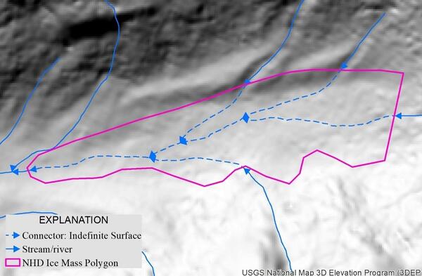
If the ice mass creates a rise in elevation and it is necessary to connect upstream and downstream features through the ice mass area, use a Connector: Indefinite Surface feature from the base of the rise to the point where flow begins to go downhill again. If a Connector: Indefinite Surface feature is used in this manner, include a comment stating, “Ice Mass Connectivity. Monotonicity cannot be enforced.”
The presence of ice masses in a collection area shall be documented in the collection report, including the source used to identify ice mass and the imagery date or the date the source was accessed. The recommended ancillary data source for glaciers and ice masses is the Randolph Glacier Inventory, A Dataset of Global Glacier Outlines, Version 7, National Snow and Ice Data Center (nsidc.org). Current imagery or NHD may also be used to identify ice mass areas.
Lines Crossing Ridges
Delineated elevation-derived hydrography shall not cross areas where the surface elevation is higher than surrounding cells. Elevation-derived hydrography shall follow channels and flow paths lower than surrounding terrain.
Elevation-derived hydrography lines crossing over ridges can create watershed delineation issues. To avoid this, ridges should be identified using geomorphic derivatives and intersected with elevation-derived hydrography lines to see if the lines cross ridges (Appendix 3).
In some cases, a line crossing a ‘ridge’ may require a Connector: Terrain Breach features. In other cases, it may indicate a misaligned line and delineated on an adjacent slope. In the most serious case, it shows a line has been derived crossing a ridge and flowing into an adjacent channel. Ideally these ridge areas will be identified and avoided as hydrography lines are generated, and algorithms can be optimized to avoid placing lines that cross over ridges.
Caution should be used in calling these ‘errors’; IfSAR and lidar surfaces contain many artifacts and scattered ‘ridge’ cells may be anomalies in the surface that are not necessary to avoid.
If streams are crossing ridges, as indicated by geomorphic derivatives, they should be evaluated to determine if they are a problem. Removing single or small clusters of or two or three ‘ridge’ cells from the geomorphic derivatives will help reduce probable artifacts.