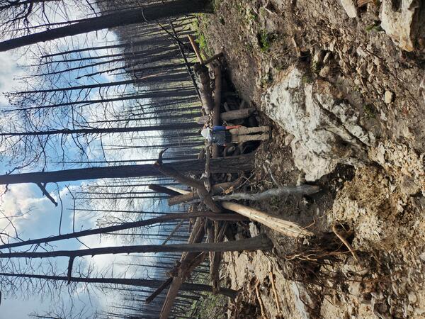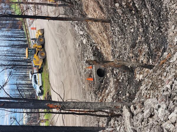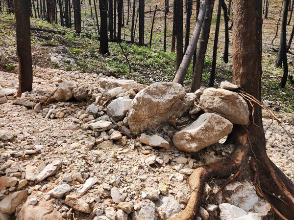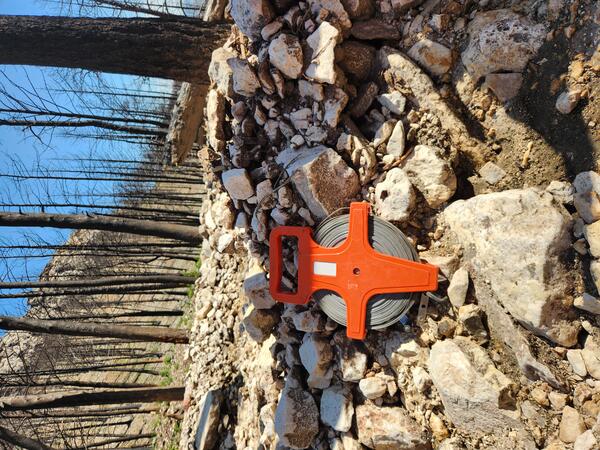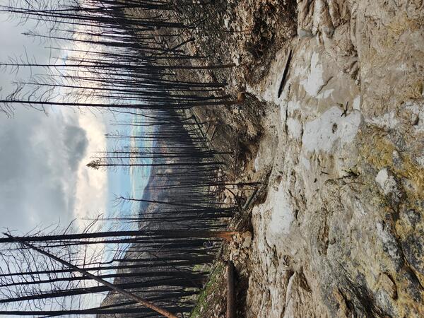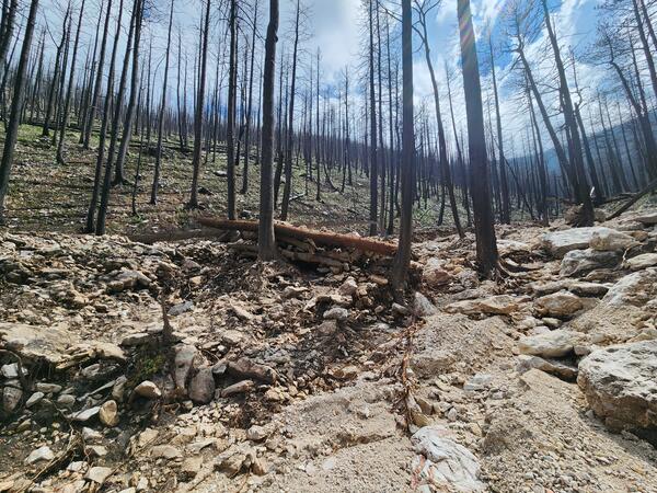
Postfire debris-flow deposit in the 2024 Elk Fire burn area
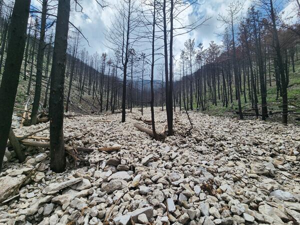
Postfire debris-flow deposit in the 2024 Elk Fire burn areaPostfire debris-flow deposit in a channel within the 2024 Elk Fire burn area near Dayton, Wyoming. Following a July 2025 thunderstorm, the channel filled with mud, cobbles, small boulders, and woody debris. This photo, taken near the watershed outlet, looks upslope from U.S. Highway 14.